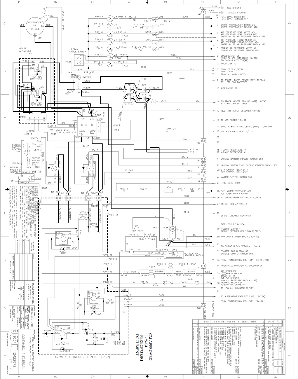
Executive summary:
Simplifying, upsizing wire, and adding mysteriously absent fuses to the LMTV’s original wiring
Step 1: Figure out what is going on here…

As you can see in the diagram above, the A1 LMTV has a 100A dual voltage alternator connected to both manual and automatic disconnects fed into a high amp, fully potted, diode pair started by a 2S2P battery system with…. I’m just kidding – about being able to see that in the diagram, that is actually how it’s supposed to be. Unless you’re an engineer (I’m not) or have spent some excruciating weeks studying it while simultaneously trying to learn to read… whatever that type of schematic is called (I’m being told it’s called a “ladder diagram”), it’s probably undecipherable or pixelated. Maybe both. By the way, that is page 3… of 20.


Highlights
- It has a dual voltage (12v/24v) 100A alternator
- That is woefully underpowered to (re)charge four 120Ah batteries, let alone power what I want it to. It is split 60A 24v, 40A to 12v.
- That is woefully underpowered to (re)charge four 120Ah batteries, let alone power what I want it to. It is split 60A 24v, 40A to 12v.
- It has a manual disconnect
- Except my A1 does not have this. So the schematics are more of a pirates code (“guidelines”) than hard and fast rule.
- Except my A1 does not have this. So the schematics are more of a pirates code (“guidelines”) than hard and fast rule.
- It has an “automatic disconnect” called a Load Balance Control Device–more on that later
- Also don’t have this, and adding this to the A1 seems to be a design decision because the alternator was so weak.
- Also don’t have this, and adding this to the A1 seems to be a design decision because the alternator was so weak.
- It has a pair of high amp diodes completely encased in epoxy in an aluminum heatsink the size of a red brick
- And left outside, in the elements, for 22yrs. These serve as protection for the vehicle to prevent damage if the batteries are connected incorrectly.
- And left outside, in the elements, for 22yrs. These serve as protection for the vehicle to prevent damage if the batteries are connected incorrectly.
- It has 4 x 12v batteries in a double series, double parallel configuration. This both doubles the voltage (series) to 24v and doubles the amp hour capacity (parallel). It’s a pretty good setup for 24v with plenty of harsh winter, “left sitting”, or deep cycle capacity
- …Until you unbalance it by taking 12v out of the middle of 24v, don’t have a frame ground from the batteries, have your cables in a configuration where one of the four batteries is left dangling without getting much charge or usage, the list goes on.
So I deleted all that crap, added fuses which were not present, upsized battery cabling, and more !
Back to the drawing board
I started highlighting paths on the diagram, going out to the truck and physically looking or following wires, and then made myself a little diagram of how it actually was, so I could then figure out how I wanted it to be.

I basically have the “A0” wiring without the load control device or manual disconnect, which does make things a bit simpler for me to remove/redo.

In addition to upsizing the alternator 24v cable I’m: correctly wiring the batteries, removing the PPD, adding busbars and fuses, a master disconnect, a remote disconnect for a winch, battery tenders, and a highly efficient 24v-12v converter in place of pulling 12v out of the middle of 24v.
Note: I got 80% of that done before summer hit, and even though NC is pretty North for a “southern” state, the summers here are brutal. It sat for 3.5mo and I was pretty worried until I got her started again in September !
Full Disclosure:
I am a full disclosure person: This site contains affiliate links. It costs you nothing but I receive a small percentage if you purchase using the above links. I would greatly appreciate it if you would support the site using them, but if not I also understand. Thanks for reading, and may every landing be gear down !

